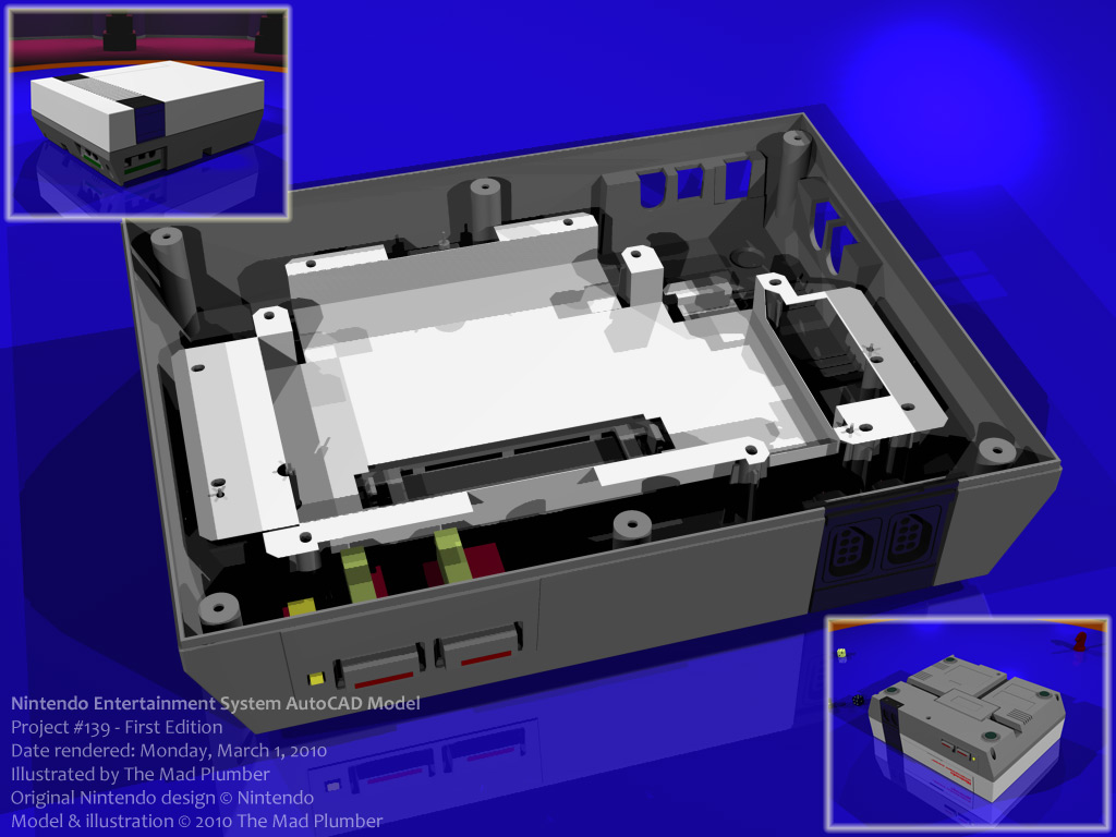
Nintendo Entertainment System AutoCAD Model (Part 2)
Thank you very much for visiting. Advanced criticism and professional advice are strongly encouraged.
The image featured in this submission is a render of an AutoCAD solid model that I had illustrated. The model resembles the 1985 Nintendo Entertainment System, an 8-bit gaming console which hosted titles such as Super Mario Bros. and The Legend of Zelda. An NES game console featured a slot for loading a single game cartridge, two ports for plugging in game controllers, and various nodes for outputting images to a user’s television set.
There was a previous inquiry as to why I used AutoCAD as opposed to dedicated three-dimensional graphics software such as Alias Maya or 3D Studio MAX. The first reason for using AutoCAD to do this project is that it is relevant to my trade. In my efforts to return to work as an AutoCAD draftsman, I attempt to build compelling portfolios to convince potential employers of my remarkable proficiency with AutoCAD. I view the ability to perform solid-modeling in AutoCAD as being the ultimate testament of an AutoCAD professional.
A second reason for modeling the Nintendo in AutoCAD instead of a three-dimensional graphics application is that the ultimate model is intended to be far more complex. The user noted that somebody else could have modeled a Nintendo with Maya or Studio in significantly less time than I had taken to do it in AutoCAD. I noted, however, that such models are little more than polygonal boxes textured to resemble a Nintendo; there is little true complexity to the model. My model is intended to resemble a Nintendo Entertainment System from and outside and the inside. The parts separate parts such as the plastic shells, the glamour plates, the buttons, the metallic casings, and the loading tray are illustrated as their own separate drawings to ultimately be united into one drawing file.
If somebody were to ask as to why I illustrated the model in AutoCAD as opposed to CATIA or Pro/ENGINEER, that would have been an excellent question. Unfortunately, I would have a pathetic answer to such to such an inquiry: I don’t have the software.
I noted in the previous submission that the definition of solid-modeling differs from software to software. In AutoCAD solid-modeling is defined by boundary representation, or B-REP. What this means is the solid shape is defined by its surfaces. In software like CATIA or Pro/ENGINEER, parametric modeling is employed in the construction of solids. In parametric modeling, constraints are defined by the CAD operator to instruct the computer as to the relationships of the geometry. From my experience, parametric modeling is superior to boundary representation.
Let me illustrate my point by explaining a problem that occurred during the construction of this model. I was adding features to the bottom plastic shell of the Nintendo. I noticed, however, that the geometry that I was adding was closer to the existing geometry than it should have been. I came to realize, much to my chagrin, that a particular feature that I had built into the shell was an entire centimeter off from where it should have been. Now, not all was lost. I had options to rectify the problem. AutoCAD has a set of solid-editing tools such as “moving faces”. Unfortunately, the geometry was very complex and if I failed to select one critical face in my move operation, the operation would either fail or I might drastically foul up the model. Instead, I “cut out” the most complex parts of the geometry, performed the “move faces” operation on the simplified geometry, and replaced the geometry that I cut out.
If I came across this same problem in CATIA or Pro/ENGINEER, all I would need to do to rectify the problem is change the constraint.
That very scenario illustrates one of the many reasons that I would have saved a considerable amount of time and aggravation had I had CATIA or Pro/ENGINEER at my exploit. Performing solid-modeling in AutoCAD takes a considerable amount of patience and creativity.
Again, I still wish I had the original manufacturing blueprints for the Nintendo Entertainment System. It would also be particularly helpful to have schematics of the small Mitsumi parts featured in the main power console. There’s only so far that I’m willing to take apart the Nintendo I have at hand.
This is the first edition of my model so that I can include renderings in my portfolio. There are parts that I have illustrated but have yet included in the final scene, as their inclusion is dependent on other features that I haven’t illustrated yet. I approximate there’s about only two or three more parts that I need to rough in, not including the screws. Future editions should illustrate a far more dynamic model, though the changes would appear to be rather small to notice.
Again, thank you for the visit and have a wonderful day.
PROJECT #139
Category Artwork (Digital) / Miscellaneous
Species Unspecified / Any
Gender Other / Not Specified
Size 1024 x 768px
File Size 144.9 kB

 FA+
FA+






Comments